

Four or five Leads
Most of PalmSens’ instruments have cables that end in four plugs with 2 mm banana connectors. These plugs show labels and colors.
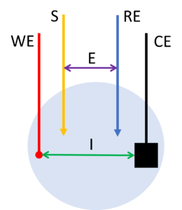
- The red plug is the working electrode lead.
- The blue plug is the reference electrode lead.
- The black plug is the counter electrode lead.
- The green plug is the ground lead.
- The yellow plug is either a BiPot (or a sense lead until 2021).
- The white plug is a sense lead.
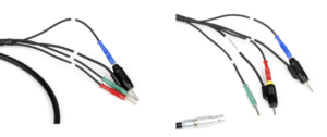
The PalmSens3, PalmSens4, and MultiPalmSens4 are available as bipotentiostats. A bipotentiostat has two working electrodes. The fifth lead of their cables is a yellow plug, which is the lead of the second working electrode.
The EmStat3+ and the EmStat4 HR have the fifth lead as well. This is also a yellow or white plug or if you have an older cable a bright red plug. These plugs are stackable and are used for the sense lead also known as working sense.
Ohmic Potential Drop at High Currents
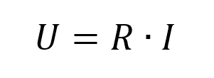
Ohm’s law is well-known (Equation 1) and usually, it is read as “To increase current flow across a resistor, I need to increase the potential proportionally.” This is correct, but so is another consequence: “When a current flows through an Ohmic resistor it will create a potential drop.”
Many electrochemists are aware of that potential drop. In most experiments and cells, the drop is negligible, but if there is a large uncompensated resistance in a cell, the potential drop can be significant. However, this should be discussed in more detail, when IR-drop compensation is discussed.
The same principle of an Ohmic Potential drop can be observed across the cable of a potentiostat. The cable is an Ohmic resistor, and the cell current is running through it leading to an Ohmic Potential drop. A typical PalmSens sensor cable has a resistance of 0.2 Ohm. If you are measuring a current of 1 µA, the ohmic drop is 0.2 µV. This is negligible. A current of 100 mA causes an Ohmic drop of 20 mV. The result would be that your electrode experiences 20 mV less than you expect. Depending on your experiment this could be a significant amount of potential difference.
Correction by the Current free Sense Lead
The Ohmic drop across the cable can be corrected with a sense lead. The sense lead has similar function as the reference electrode lead. It measures a potential difference, and no current is supposed to flow. Ideally no current flows, in reality a very small current is required to measure the potential.
The sense lead is connected to the working electrode. It measures the potential at the working electrode without any current flowing. Due to its current free state, no IR-drop occurs in the sense lead and the applied potential at the working electrode is measured. The potentiostat can use this information to correct the IR-drop inside the working electrode lead.
This means if the current at the working electrode times the resistance of the working electrode lead reaches a significant potential drop, a sense lead is required to compensate for the Ohmic drop.
This is also the reason most potentiostats designed by PalmSens do not have a sense lead. Most of our potentiostats support current up to 30 mA, 20 mA, or 3 mA. These currents lead to a 6 – 0.6 mV Ohmic drop inside the working electrode lead, which is not significant for most setups.
The EmStat3+ and EmStat4 HR support currents up to 100 mA and 200 mA, which result in a significant potential drop.
2, 3 and 4-Electrode Measurements
Most of PalmSens’ instruments only offer a 2- or 3-electrode setup. The EmStat4 HR is also suitable for a 4-electrode setup. To understand the purpose of the 4-electrode measurement each setup (2-, 3-, and 4-electrodes) will be discussed in this section.
2-Electrode Setup
To make a 2-electrode setup just combine the counter and the reference electrode. The counter electrode of our cables is stackable, so you can conveniently combine them. You connect the working electrode (and sense) lead to one electrode and the combined counter and reference electrode lead to the other.
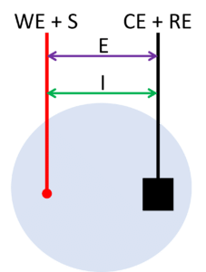
During a measurement in a 2-electrode setup, the potential will be applied between the two electrodes and the current will flow between the same two electrodes (see Figure 2). This means the applied potential includes the potential drop across the working electrode’s interface, the potential drop across the solution, and the potential drop across the counter electrode’s interface. Any changes at the counter electrode will influence the result. If your counter electrode is expected to be stable during the measurement due to low currents or a short duration of the measurement, you can use this setup almost equivalent to a 3-electrode setup. Otherwise, this setup is only used for applications where the full cell potential is an interesting parameter, for example, fuel cells or batteries.
3-Electrode Setup
The 3-electrode setup is the most common setup during electrochemical measurements. The working electrode (and sense) will carry current and potential in this setup as it does in the 2-electrode setup. The counter electrode will still carry the current, but the potential is controlled between the working and reference electrode (see Figure 3).
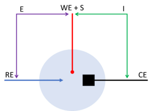
This has the advantage that the potential drop across the counter electrodes interface is not included in the applied potential. Another advantage is that the reference electrode does not carry any current and will thus keep a stable potential during the measurement. This means the potential of the working electrode is more accurate.
4-Electrode Setup
In the 4-electrode setup, the working electrode is split into two electrodes: the working electrode and the sense. The potential is applied between the sense lead and the reference electrode. The current flow between the working electrode and counter electrode.
This way the potential drops across the counter or working electrodes’ interfaces and thus the corresponding reactions are not contributing to this measurement. Only processes across the solution and obstacles, for example, a membrane, between the sense and the reference electrode contribute.
This setup is usually only used to research solid-state electrolytes, membranes, or liquid-liquid interfaces.